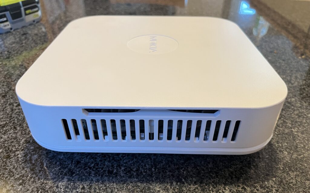
Today I’m converting my Nokia Flexi Zone Multiband Indoor Pico BTS model FW2IRA to use external antennas. It’s a 2×2 LTE band 66+46 eNodeB about the size of a couple dinner plates stacked up. I need external antennas because, like my previous conversion of a Nokia FWFF, I’m going to pipe the radios into a Willtek RF Shield so I don’t make mobile carriers angry.
The Multiband part of the name (and the “2” part of the model number) indicate these are second generation Nokia LTE Pico BTSs which support two LTE bands each. The first generation (like the FWFF) only supports a single band.
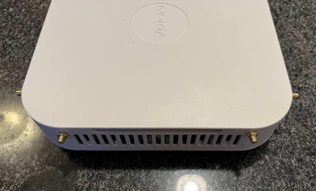
Here I’m starting with the top of the unit off, looking at the four antennas that I’m going to remove.
The antennas themselves just screw into the huge heatsink, but unfortunately to disconnect their cables we have remove the heatsink because the connectors are far underneath:
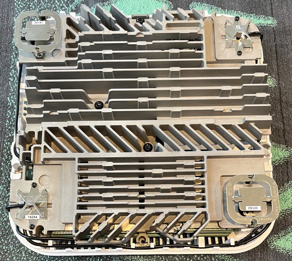
While I’ve got the heatsink removed, let’s take a look inside.
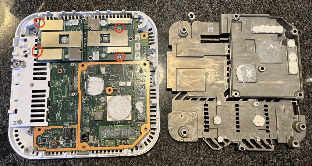
Immediately you can see a huge CPU, another big chip that’s probably an ASIC, a Lattice FPGA, a bunch of DDR3, and two RF cards. Nokia Flexi Zone Picos support a huge number of bands and to manage that the base BTS is the same but the RF cards are changed to support each frequency combination.
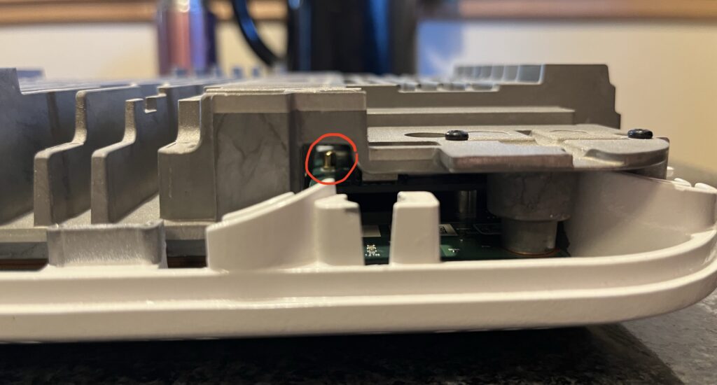
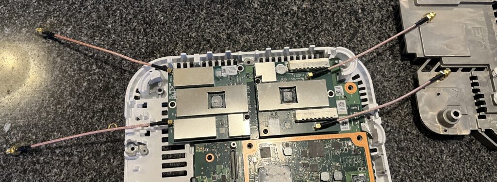
Now that I have access to the antenna connectors, I’m going to snap in the SMA pigtails.
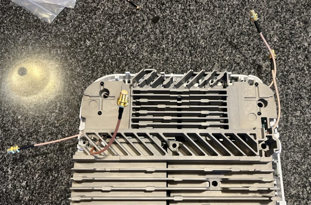
And then screw the heatsink back on and route the pigtails around it:
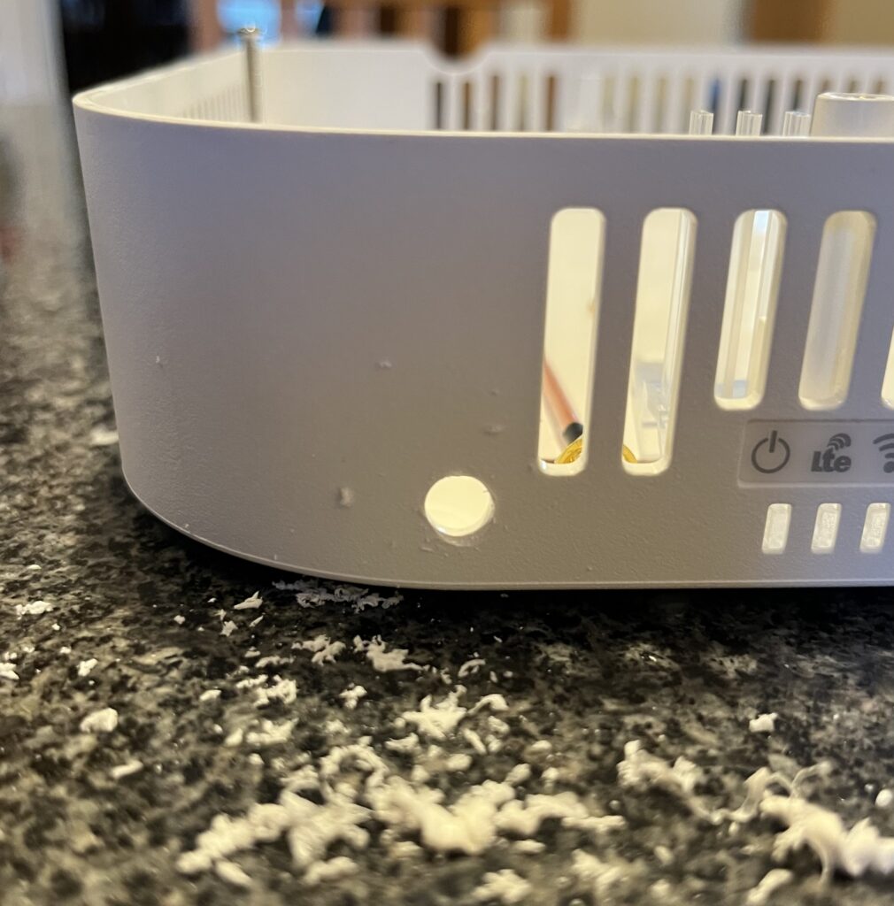
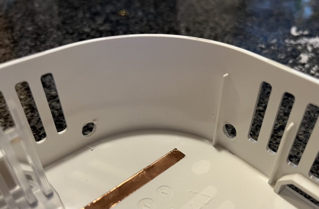
Next I drilled four holes in the corners of the top case for the SMA connectors to screw into:
And repeat a couple more times…
I tightened up the SMA connectors on the outside:
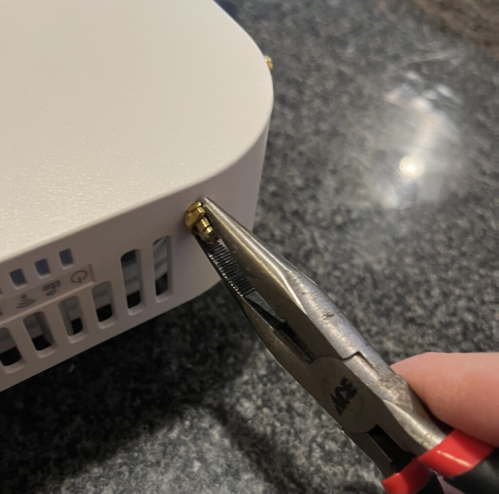
And now I have four external antenna connectors on the FW2IRA. It’s definitely not as elegant as the pre-existing SMA connector holes on the FWFF but it’ll work.